|
|
|
|
|
||||||||
|
|
|||||||||
| Home | Forums | Register | Gallery | FAQ | Calendar |
| Retailers | Community | News/Info | International Retailers | IRC | Today's Posts |
 |
|
|
Thread Tools |
 January 26th, 2015, 14:14
|
#1 |
|
Squid Porn Superstar, I love the tentacles!
|
Installation Guide for Simple MOSFETs
So MOSFETs are becoming a much more common thing for AEG users to have nowadays, so companies like Gate are making fancy looking FETs for the mass markets. They come with schematic diagrams, which are straightforward to those who are technically inclined, and rocket science to those who aren't. This is a simple schematic of the single signal wire method that was posted by someone in another forum. For a step by step guide with pictures, keep scrolling down.
 I guess the other problem is that the most durable MOSFETs are the hard to source BTC units, Extreme Fire MOSFETs, and home brew simple MOSFETs. Aside from BTC, home brew FETs based on the IRLS or IRLB 3034 FETs are my favourite FETs to use and install due to their size, simplicity, and durability. They are small enough to install inside some mechboxes, yet durable enough to withstand a 14.8V Li-Po fully charged to 16.8V powering a 10:1 DSG cycling at over 70 RPS. There are lots of guys in the U.S. that make and sell these, and as far as I know there are very few in Canada that make and sell them. If you would like to get a hold of some, PM me. They generally come with no installation instructions, but include all the things you need to install one: wires, heat shrink, male deans, and motor tabs. All you really need to know is the signal wire and motor negative wire usually come out the same side. The negative battery wire comes out the other side. I make these FETs, and I've installed maybe fifty of these units, with no reported failures to date (excluding one user who incompetently decided to open his box himself and fuck up the wiring). There are two basic installation methods I use: a single signal wire method, and a double signal wire method. I prefer the single signal wire method for V2 gearboxes because the wire routing method makes it less likely that a signal wire will be chewed by the motor. The dual signal wire method is more efficient, and is better for guns where the trigger contacts can be accessed on the outside of the gun, wire is routed outside of the gearbox, and wires can be soldered to the motor. I use this method for V3, V6 and V7 gearboxes. What you will need Required: -basic soldering skills -competence in basic gun work -soldering iron -solder -flux Suggested: -vice, helping hands, or something that can hold the things you're soldering -soldering stand -extra heat shrink Single Signal Wire Method This guide will assume you know how to assemble and reassemble a gearbox. First you will want to remove your trigger assembly. Remove this screw to take it apart and take the contacts out. Some assemblies will have a side screw as well. 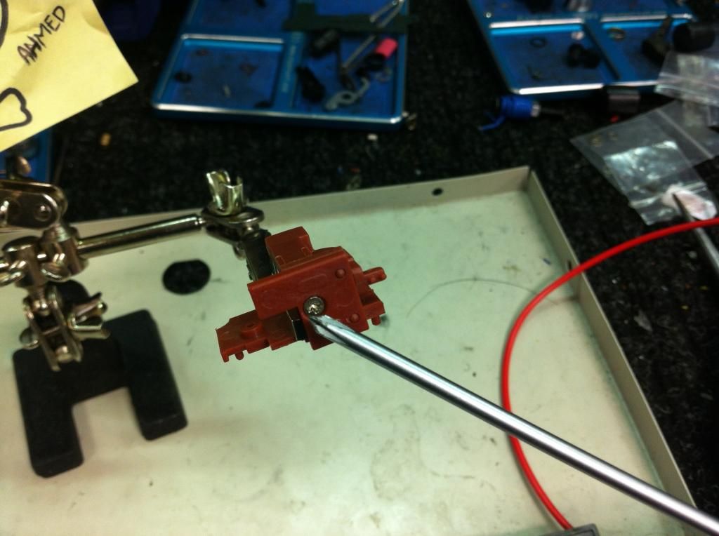 You will end up with something like this. 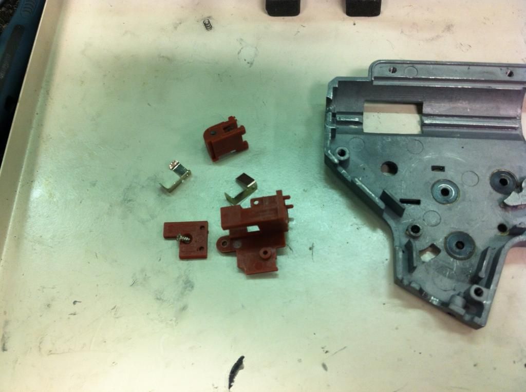 Take your POSITIVE wire, and measure out the correct distance you will need to go from your trigger contact to your motor. Make sure the other end of the positive wire is long enough to reach to where your battery connector will be. In my case, its the buffer tube. Too long on either side won't hurt, you can cut it later. 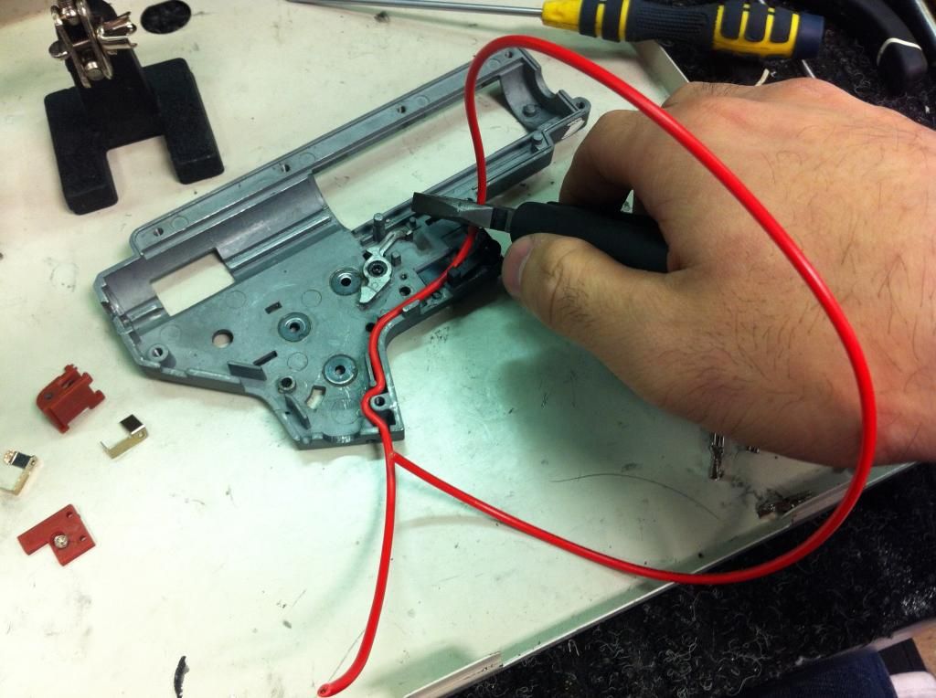 Now this is where some people cut the wire and solder them together. That's totally fine. I prefer to remove the insulation, as this will result in less resistance. 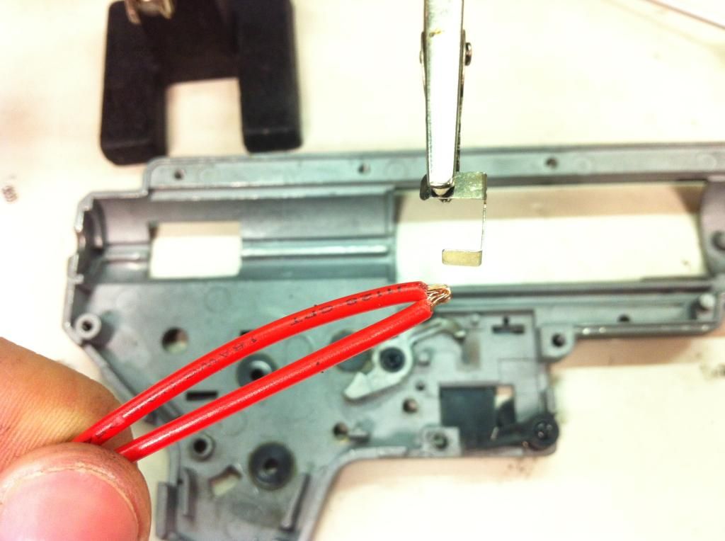 Now apply flux, and solder that to the bottom trigger contact. Heat shrink isn't a necessity, but it doesn't hurt to put some on. I recommend soldering to the bottom contact because this way it is easier to route the thicker wires around the safety lever. 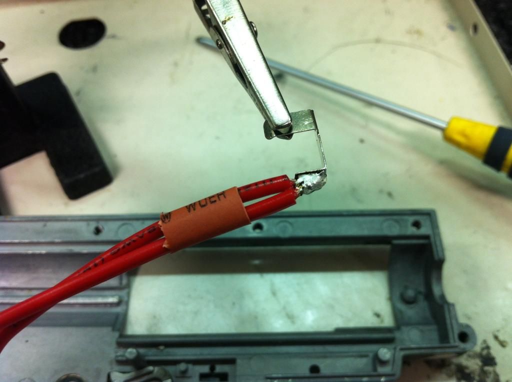 Most 3034 based FETs will be pre wired and pre heat shrinked. Take your signal wire and measure out the length you will need for it to reach to your other trigger contact. Make it a bit longer than it needs to be, so that it will be slightly longer than your negative wire so the thin signal wire won't snap if you pull by accident. 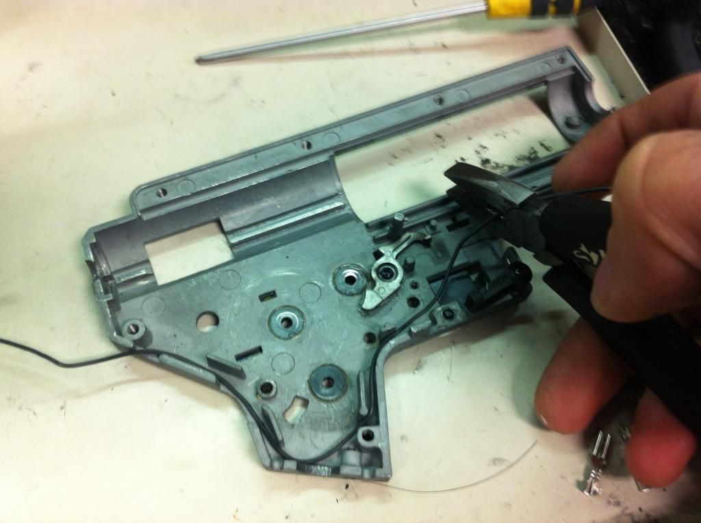 Apply flux and solder. Again, heat shrink doesn't hurt. 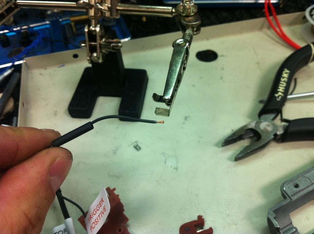 Your two trigger contacts should now look like this. 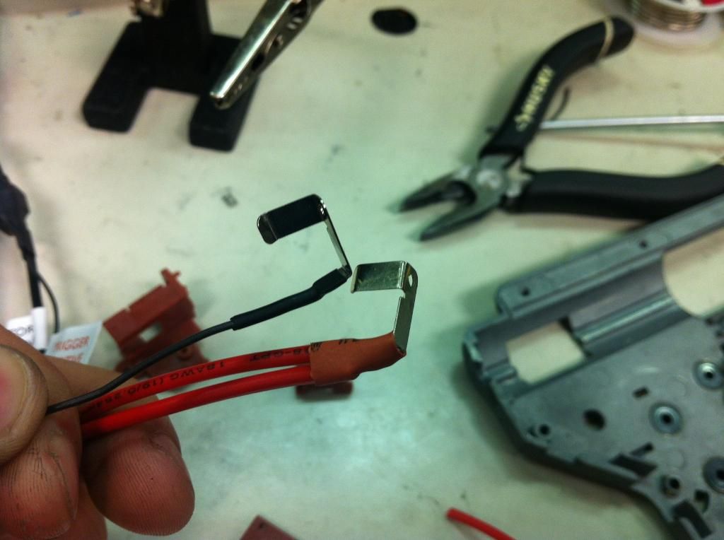 Reassemble your trigger assembly, and put it in the gun. I recommend routing the wiring like in the picture. Signal wire on the bottom, positive motor wire on top of that, and the positive battery wire at the very top. 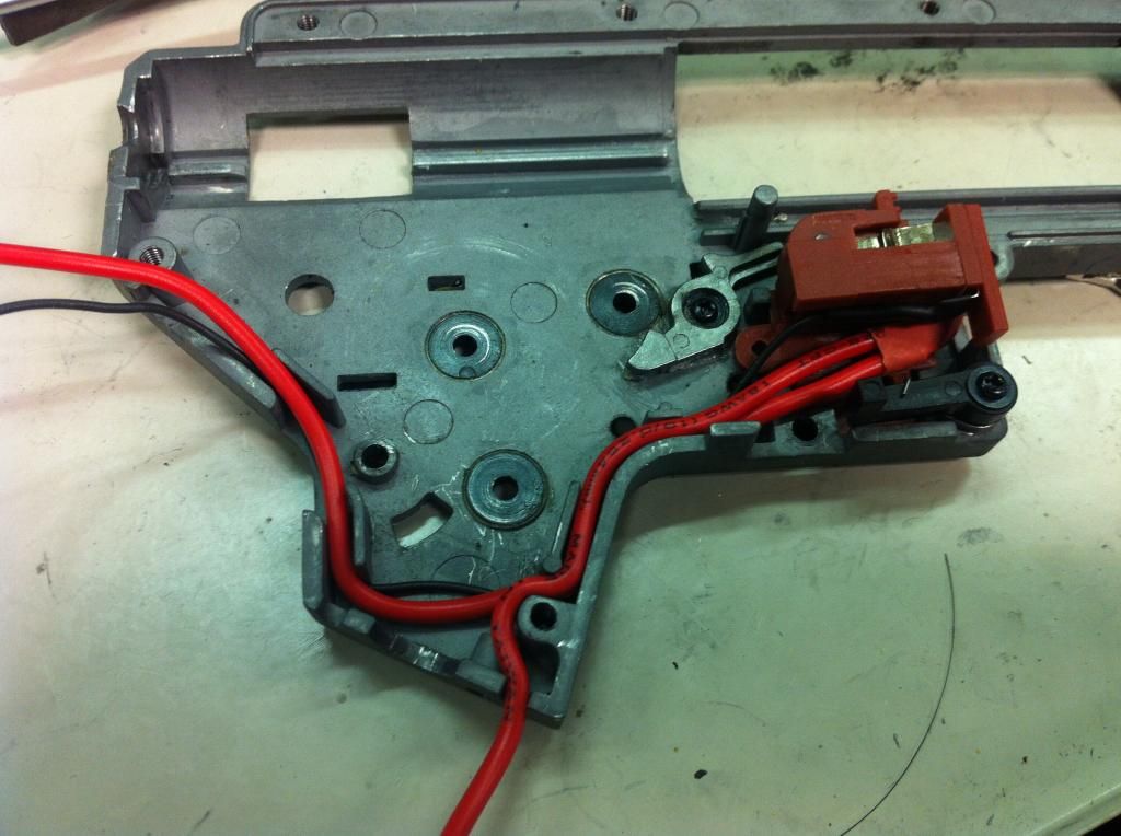 Now you can take your negative motor wire, and place it in the gearbox. Stick a motor in to see how much motor wire you need, then cut it to length. 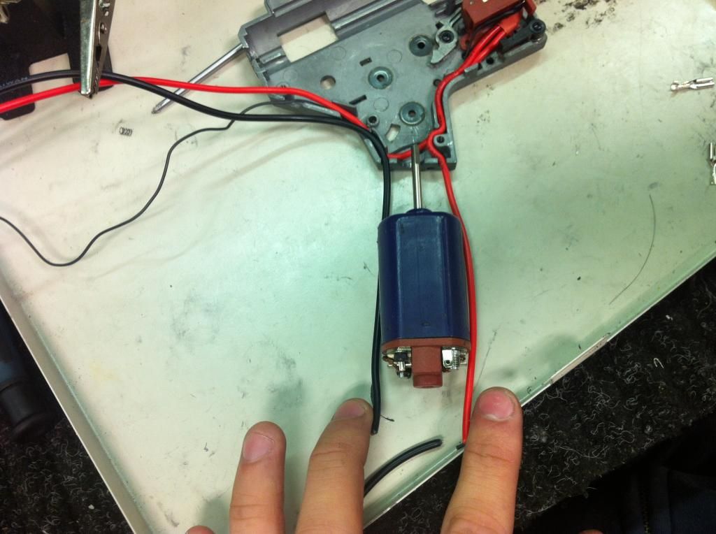 Soldering motor tabs is something I see very few people do correctly. Most people crimp and then solder from the outside. The result is extremely messy and is useless because all of the solder is on the outside, and little to no solder is inside the connector attaching it to the wire. What you should do, is apply flux to the wire ONLY. 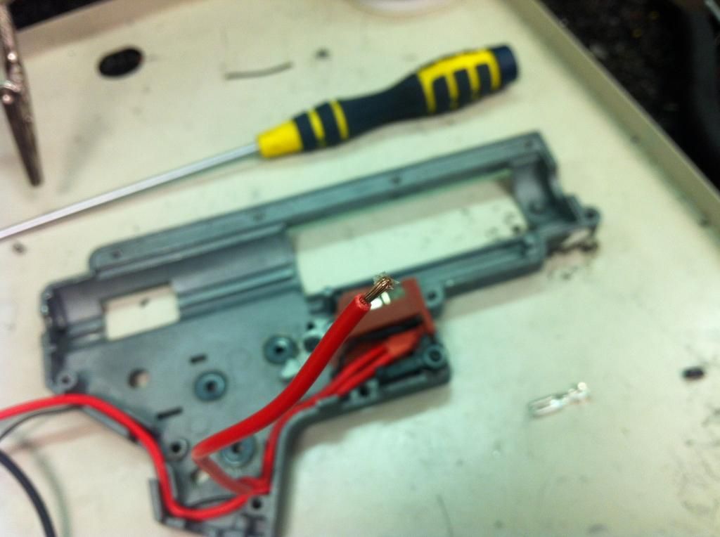 Next take a pair of pliers, and crimp the motor connector on to the wire. Make sure all of the flux stays on the inside, on the exposed wire and on the inside of the motor connector. This way when you apply solder, it sticks to the inside instead of the outside. 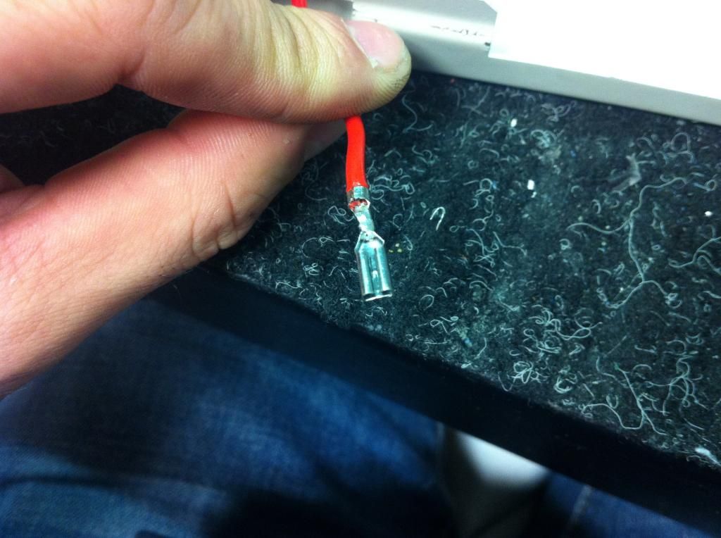 Apply heat shrink. 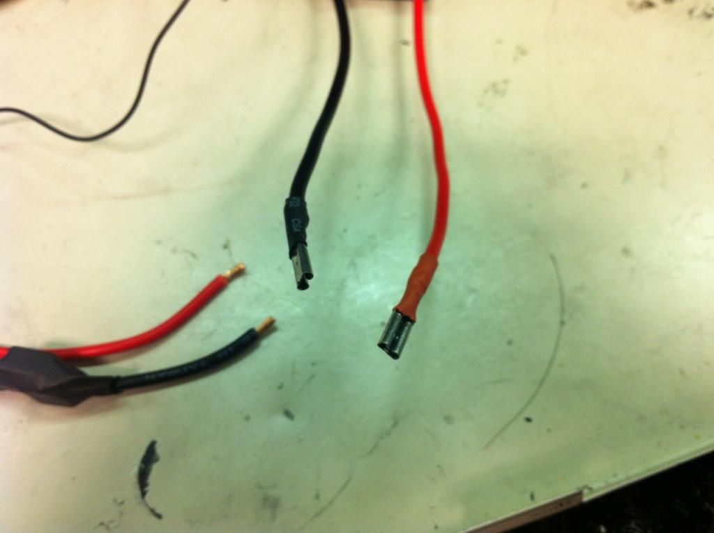 Solder your connector on, DON'T FORGET TO HEAT SHRINK BEFORE YOU SOLDER! I used to always forget haha. 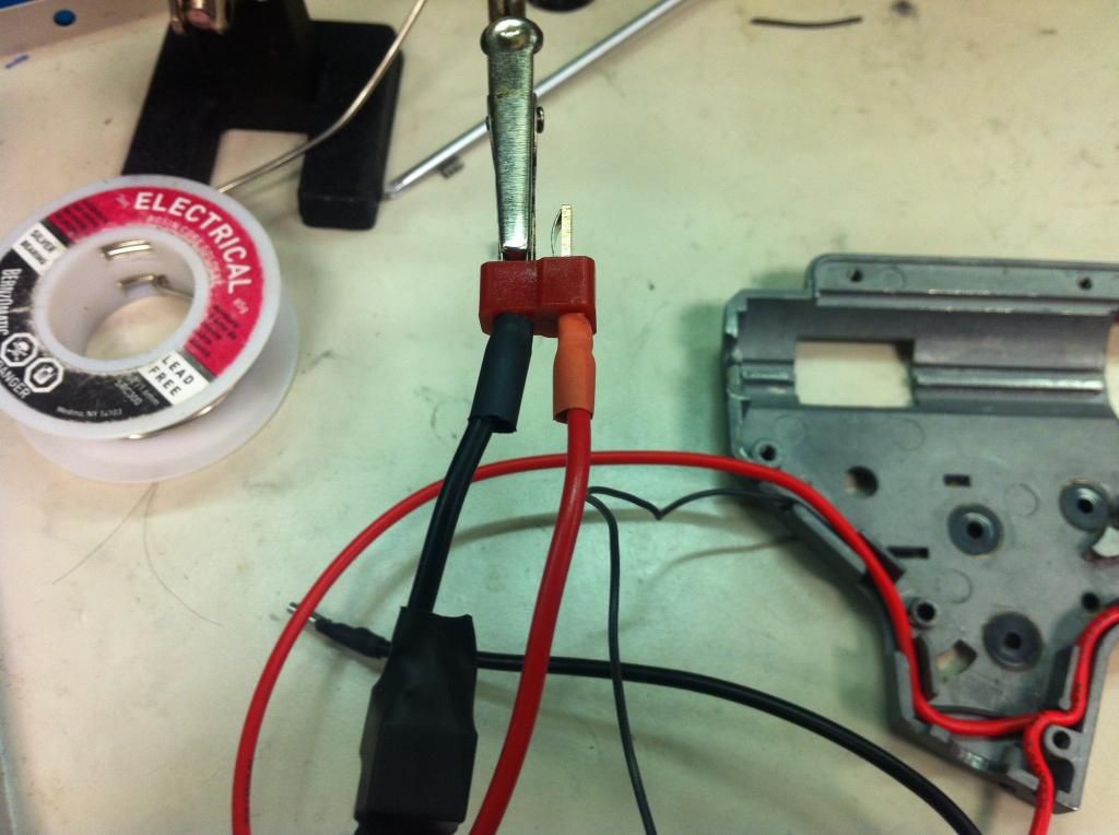 You're done! Your wiring harness should look something like this. Now you can reassemble your gun and go zug some noobs. 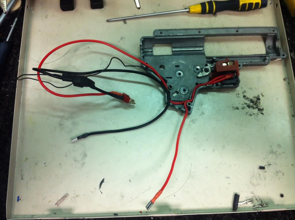 If you're feeling adventurous, you can try installing the FET inside the mechbox. In VFC, Lonex and Modify mechboxes you can fit them underneath the spring guide, and behind the spur gear. You will have to make a hole under the spring guide for the negative battery wire to come out of, and you will have to remove material from the wire hold downs on the top of the mechbox. This is my favourite installation method. 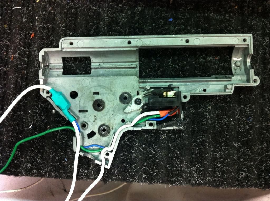 Dual Signal Wire Method This installation method is the easiest method, but you have to make sure you install it correctly. Soldering the second signal wire to the wrong motor tab will result in damage to your FET unit. This is a V3 mechbox. If you are good at soldering, you can do it without taking your gearbox apart. If you are mediocre at soldering, I strongly suggest taking your gearbox apart so you don't melt your contacts. First thing's first, desolder your original wires. 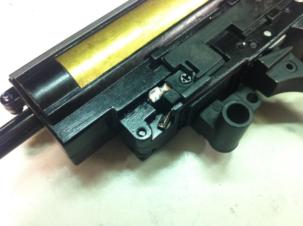 Take the signal wire that's attached to your FET, and measure out the length you need to reach the contact from where you want your FET to be placed. Make sure you keep the rest of the signal wire you snipped off intact, you will need it as your second signal wire.In my case, it will be going in a front wired G36. 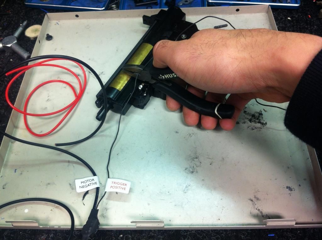 Solder it to the trigger contact. 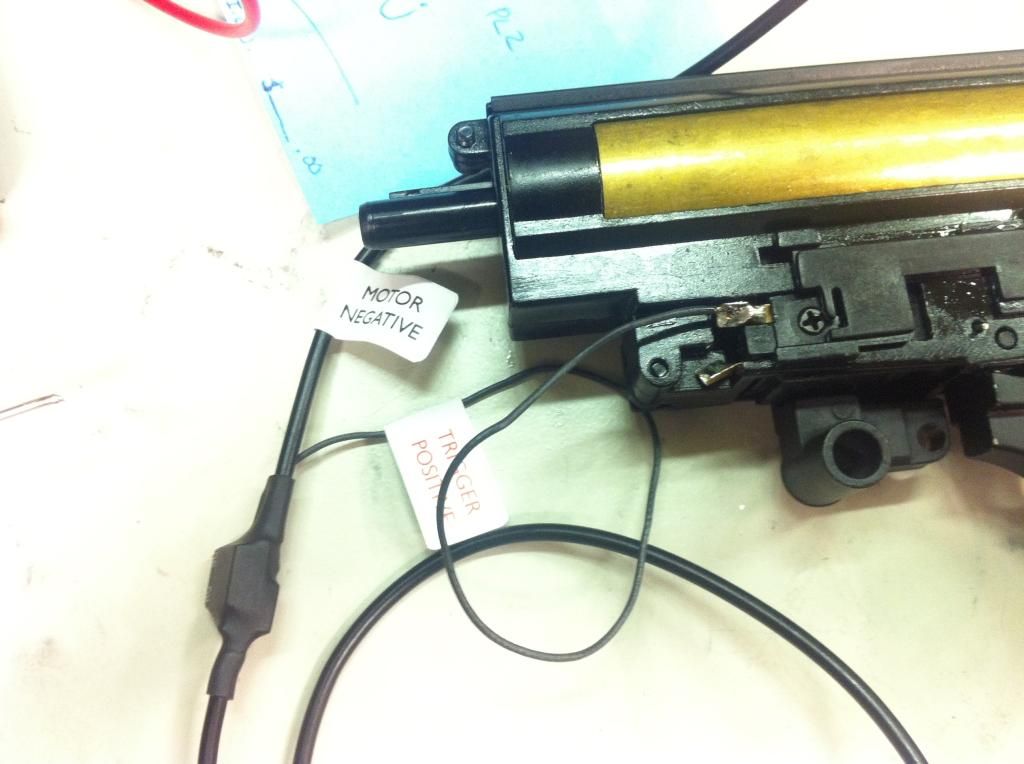 Next, do the same thing with your NEGATIVE motor wire from your FET. 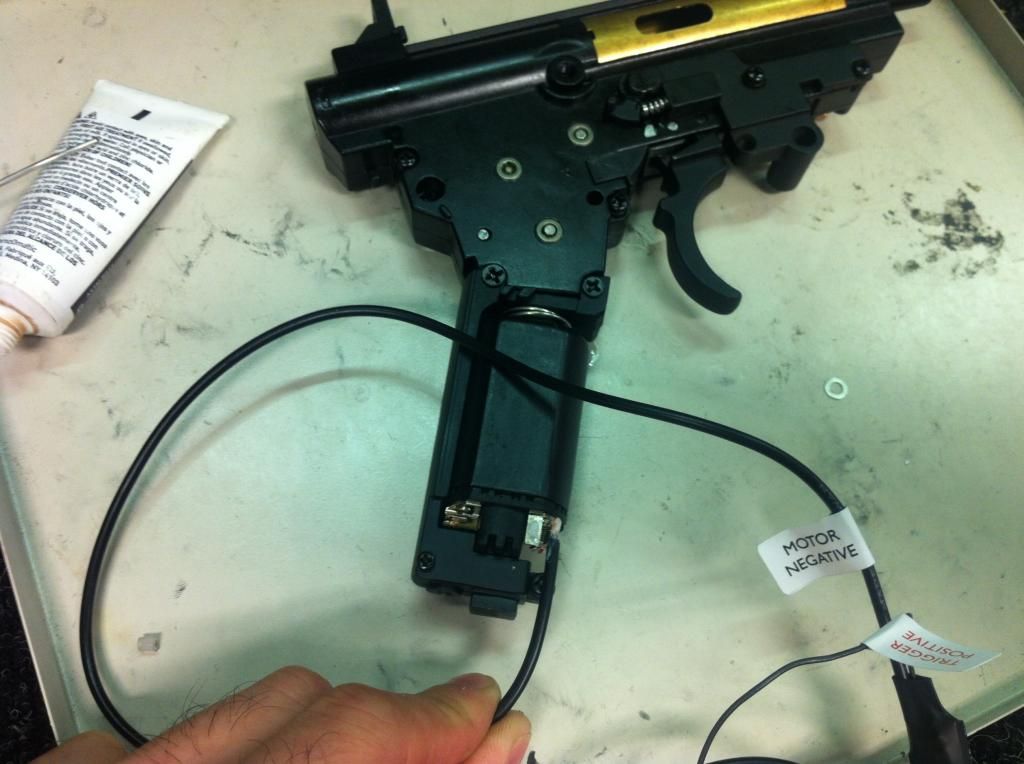 Apply flux and solder. Clean solder joints are good solder joints, messy ones are bad. Just stating the obvious here. Heat shrink is useless here. 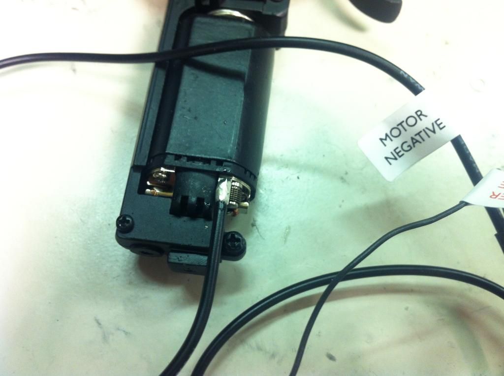 Take your second signal wire, and attach it to the end of your positive wire. 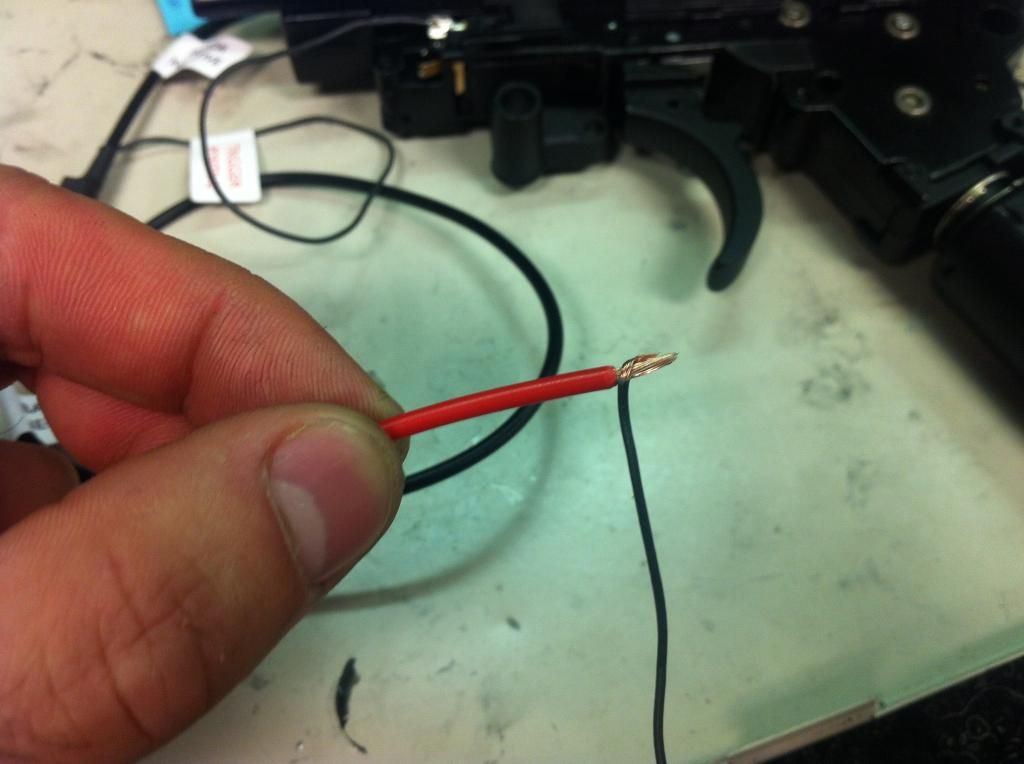 Solder them both to your positive motor tab. 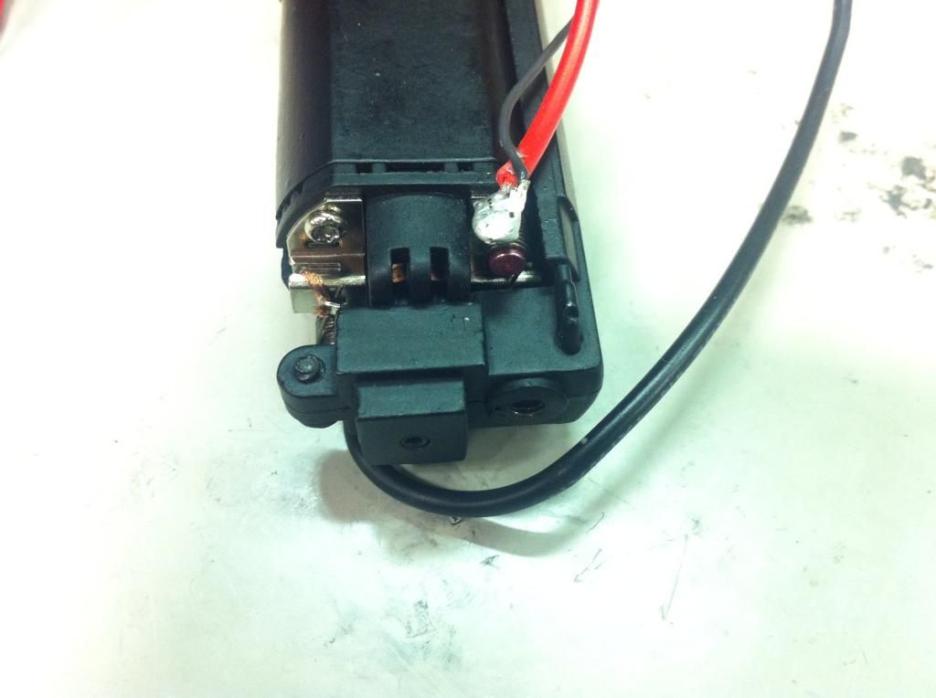 Now take your second signal wire, and measure the length you need for it to reach your other trigger contact. Cut it, and solder. 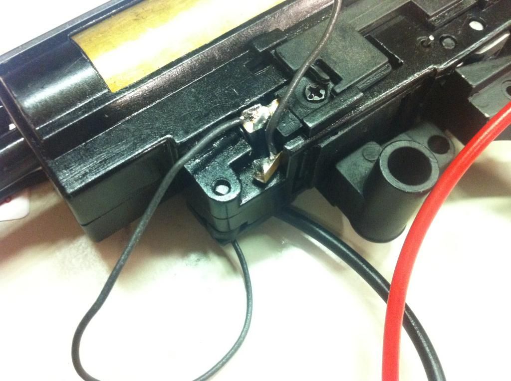 Now take your positive and negative battery wires, route them as if they were in your gun, and then cut them to length together so the length will be more or less even. Solder on your connector, DON'T FORGET HEAT SHRINK! lol 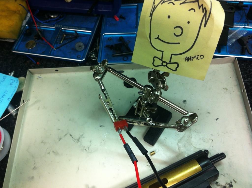 You're done! My result looks like this. Obviously with this method every installation will look different, depending on what mechbox you used and where your battery is located. 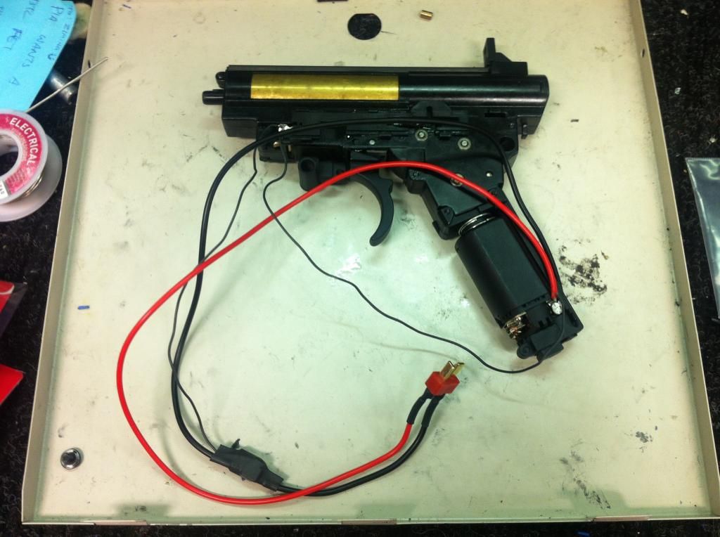 __________________________________________________ __________ So that's how I install MOSFETs. Obviously there are many ways to wire them, some ways are better than others. This is just how I do it. I hope this helped some of you guys out. -Z Last edited by pestobanana; January 26th, 2015 at 18:55.. |

|

|
|
January 26th, 2015, 15:59
|
#2 | |
|
|
Nice write up! This should be stickied!
__________________
 Quote:
|
|
|
|
|
|
January 26th, 2015, 16:09
|
#3 |
|
|
Now there is a proper explanatory post. The folks in Northern Toronto are lucky to have you in the area doing this kind of quality work.
Not sure about the bowtie though in the selfie.
__________________
|
|
|
|
|
January 26th, 2015, 17:12
|
#4 | |
|
|
Quote:
|
|
|
|
|
|
January 26th, 2015, 18:04
|
#5 |
|
|
Awesome write-up! I definitely second the sticky!
|
|
|
|
|
January 26th, 2015, 18:17
|
#6 |
|
|
You make this look so easy. It's like those Cooking Channel tutorials. "estimated cooking time: 20 minutes, serves 4". But when you do it, you're 1 hour in and it looks nothing like what's shown on TV and you're all like D:
|
|
|
|
|
March 2nd, 2016, 18:36
|
#7 |
|
willing to perform services in a dark alley that may or may not leave you satisfied for a title. GFE = 1, looks = 2, BBFS for an extra $50.
|
Really great write up! Sticky worthy for sure!!!
|
|
|
|
 |
|
||||||
| Bookmarks |
|
|
 |
|