|
|
|
|
|
||||||||
|
|
|||||||||
| Home | Forums | Register | Gallery | FAQ | Calendar |
| Retailers | Community | News/Info | International Retailers | IRC | Today's Posts |
 |
|
|
Thread Tools |
 July 6th, 2013, 15:25
|
#1 |
|
|
WIP Tanio Koba/KJW M4A1 Carbine V1 Full Takedown Guide *56K DIE*
**WORK IN PROGRESS** July 6th, 2013
I did not know what thread to put this in so for now I thought airsoft gun discussion would be best. If an admin wants to move it to another category that is fine. **56K DIE WARNING** Good day Airsoft Canada and Airsoft enthusiasts.  So you've purchased a KJW M4 Gas Blow Back Rifle and either something terrible has gone wrong or just went to upgrade something. This guide will be perfect if you are unsure of where to begin. This is a dis-assembly/reassembly guide on how to take apart everything on your KJW/Tanio Koba M4A1 V1 Rifle. Now I am far from being a professional at making guides or take down tutorials. I've scoured the internet for this guide and no one has done it. So I decided to take matters into my own hands and give it a shot. So I am asking the community to assist me in this endeavor. I will be giving credit for services rendered. Now please bare with me as this is the first breakdown I have written and produced. I'm expecting criticism to improve the pipeline So if you have a better way of doing certain steps I would like you to send me a message and I will test it and if proven correct I will make the adjustments.(As well give credit) Now remember this is a guide for the version 1 carbine. If you have a V2(Version 2) or CQB(Close Quarters Battle) version your dis-assembly may vary. This is where the community can come in as I do not own a V2 bolt to take apart. This guide may not be 100% correct so please take caution. I do not take responsibility for any bad information, mishandling, damaged parts during take down or personal injury that may occur during this guide. Please do so at your own risk. This guide will go through the most obvious to the more difficult. So be patient as this a thorough guide. As of right now this guide consists of roughly 250 photos. Photos were taken with a Nikon D3000 Body Lens:55-200mm VR w/ SB-400 Flash. I would of made a video but this body does not have a video feature. This guide will go through 4 main categories. 1.General Take Down 2.Upper Receiver/Barrel Group(Hop up)/Bolt Carrier 3.Lower Receiver/Trigger Group 4.Magazine At the bottom of the guide will list Modifications and where to purchase upgrades/replacements. For the first few weeks of this take down being posted I will log in everyday to make sure that the guide remains updated. GENERAL TAKEDOWN  So before we get started safety first. Magazine out, Selector switch set to safe and make sure no bb is chambered in the hop up. If so remove by firing. ================================================== =========  Remove the carrying handle by turning the nuts counter-clockwise. "Lefty losey, Righty tighty" ================================================== =========  If you have an issue like I do where your carrying handle is secure and it stills moves along the rail, this solution may work. A single piece of electrical tape below will keep it snug against the upper receiver rails. ================================================== =========  Punch or by hand remove the back pin till you can split the upper and lower receivers. Some models have a very tight fit and require a punch to remove as shown in the picture. ================================================== =========  Swing open the upper receiver from the lower. ================================================== =========  Compress the Charging handle lever and pull out to remove the bolt carrier. ================================================== =========  You should look like this. If you have a V2 bolt it will not have a rubber band so do not panic. How do you know what bolt you have?  *Picture provided by Cradle airsoft* V1 on the left, V2 on the right. ================================================== =========  Remove front receiver pin and then split the upper and lower. ================================================== ========= Upper Receiver/Barrel Group/Bolt Carrier  ================================================== =========  **Flash Hider threads are REVERSED** Right = Loose, Left = Tight. THIS IS THE ONLY EXCEPTION! Start off by removing the flash hider, you may have noticed that there is a grub screw. If you notice that it's just spinning when you are turning clockwise to remove you may have to either A) Tighten the grub screw which will remove both at the same time or B)Remove the grub screw and slide off the flash hider exposing a brass tube which when then have to be removed either by pliers or wrench. Be sure to use a rag or cloth between the brass tube and the tool to avoid scratches. Be careful do not loose the nickle nut with the flash hider. ================================================== =========  Remove the outter barrel, if it does not easily slide off it may be secured by a grub screw. Please proceed to next step. ================================================== =========  Remove or Punch out the two pins securing the front sight post. ================================================== =========  Slide off the forward sight post. For those who were not able to remove the outer barrel look for a grub screw on top and remove it and it will now slide off. ================================================== =========  Slide off the retaining cap for the handguard. The gas tube should also be easily removed at this step. ================================================== =========  This is where you should be. ================================================== =========  To remove the hand guards you must pull the delta ring towards the upper receiver while at the same time pull up or down on the hand guard depending which one you are removing. ================================================== =========  With the hand guards removed. We must remove the delta ring. KJW manufacturer standards put this on extremely tight. Some elbow grease may be required to remove this ring. Use the AR Wrench tool that came with the gun. If you do not have one you can use a pair of vice grips or a wrench, this will damage/scratch the teeth on the delta ring though. "You've been warned!" Capt. Marcus Chaplin USS Colorado. ================================================== =========  Now we can remove the outer barrel from the upper receiver. ================================================== =========  This step is optional if you need to remove the dust cover from the upper receiver. Please take note of the orientation of the spring. One side is longer than the other. Short up long down. Removing this is as simple as pulling out the rod in the direction of the barrel. ================================================== =========  To remove the hop up, Look inside the upper receiver and get a flat head screw driver and remove the screw. be careful when removing the screw there are small pieces which will fall out that look like the photo below.  ================================================== =========  Now to remove the hop up plate look into the spout of the upper receiver and remove the nickel plated screw which is highlighted in the photo. ================================================== =========  Swivel the feeding lamp into the receiver and then take it out. At the same time the hop up plate will come out with it. The photo below is to show the orientation of the spring and plate during reinstallation.  ================================================== =========  With the hop up unit completely disassembled we will now separate the outer barrel and inner barrel. Remove the grub screw near the hop up opening. ================================================== =========  Once removing the grub screw it should slide right out. ================================================== =========  Now to take a part of the hop up chamber. Get a flat head screw driver and slowly and carefully pry the brass ring off. It's on there good so it may take a bit to get it off. ================================================== =========  The chamber will fall apart once the brass ring is removed. Now you can pop off the rubber and expose just the inner barrel.  For those wondering the difference on the KJW inner here is a picture of top down and profile shot of the inner barrel. This is a reference for those who want to dremel an AEG barrel to make it work with this rifle. ================================================== ========= BOLT DIS-ASSEMBLY  Bolt Carrier Dis-assembly. ================================================== =========  To remove the charging handle lift up and push it forward until it's removed from the guide rod. ================================================== =========  Remove the guide rod ================================================== =========  To remove the piston you will need an allen key. This part has factory lock tight(red) Which makes this part is extremely difficult to loosen/remove. I recommend the technique shown in the picture below. This will allow you to safely remove without scratching. You will need a pair of pliers/vice grips and a rag/cloth. **NOTE: Be careful, A rag will stop most of the scratching but if you wrench too hard and it can still scratch**  ================================================== =========  To get to the valve you must remove a small screw as highlighted by the picture. ================================================== =========  Sometime the screw will get snagged. In that case use a small screw driver and push the valve back then pull out the screw. ================================================== =========  To remove the cylinder from the rest of the bolt a small pin needs to be punched out. See highlighted picture to know where pin is. ================================================== =========  These are all the parts of the bolt carrier. ================================================== ========= [SIZE="5"]LOWER RECEIVER/TRIGGER GROUP DIS-ASSEMBLY[/SIZE  ================================================== =========  Remove the stock by pulling the latch down and sliding the stock off ================================================== =========  Push the buffer retainer down to release tension on the buffer spring/bolt. Be careful the bolt will launch out. Put your hand on the buffer before pushing it down. ================================================== =========  If it gets stucked half way as seen in the photo, all you need to do is grab a small screw driver and press down on it again. This time it should come all the way out. Be sure to hold the buffer or it will launch out and could cause damage. ================================================== =========  Remove the buffer and the spring. ================================================== =========  Use a flat head screw driver and remove the buffer tube cap. ================================================== =========  Remove the grub screw located between the 5th and 6th adjustment hole. ================================================== =========  Remove the receiver extension from the buffer tube. ================================================== =========  Remove the receiver end plate ================================================== =========  Remove the Buffer tube by twisting counter-clock wise. For those who have a plastic receiver and wish to keep it! DO NOT DO THIS STEP! YOU WILL BREAK THE LOWER RECEIVER. KJW puts a combination of steel nut and lock tight to make sure that you CANNOT separate the buffer tube from the steel nut/lower receiver. But if you have a KJW metal lower or just another lower in general that you will replace it with, by then all means go to town! ================================================== =========  Buffer tube now removed. ================================================== =========  punch the pin holding the bolt catch. See high lighted image. ================================================== =========  Once the pin has been removed. Three items will be free. The bolt catch, spring and pin. ================================================== =========  Remove the magazine catch by pressing the magazine catch button all the way in. ================================================== =========  With the button all the way pressed. You will spin the magazine catch counter-clockwise to remove it. Once removed three items will become free. The magazine catch, magazine button and spring. ================================================== =========  Removing the pistol grip will require a long allen key. The grub screw is at the very top of the grip. ================================================== =========  When taking off the pistol grip be careful as a spring and fire control selector detent may fall out. ================================================== =========  If it doesn't fall out carefully pull it out. You will notice after you take the grip off your selector switch will be very loose and not snap anymore. ================================================== =========  Remove the buffer retainer screw ================================================== =========  When you remove the buffer retainer screw, three more pieces will become loose that you must collect. Buffer retainer, screw and spring. The blue bit comes with plastic receivers due to the fact that the channel it sits in is deeper on plastic receiver than metal ones. ================================================== =========  Remove the front pin, there will be a detent and spring keeping it in place. Give it a little tug and it will come free. Be careful not to lose these pieces below. Without this your pins will fall out when in play. That will be bad.  Three images above, you notice the very small allen where you took out the buffer retainer screw. This screw stops the take down pin from falling out. There will be another detent, spring and unique to this one a screw. These are very small, keep track of them. ================================================== =========  You are now venturing into the trigger group. lets start off with removing the selector fire switch. ================================================== ========='  You are going to pull the auto sear towards the hammer. When you do this the selector switch should come out freely with minimal resistance.  ================================================== =========  The high lighted spring is called "Valve Lock Plate Spring" ================================================== =========  Pull it away so that it's no longer underneath the valve lock plate. As seen in the photo ================================================== =========  Now remove it and set it aside.  Punch the pin right above the selector switch. ================================================== =========  These are all the parts from top to bottom. Pin, Auto Sear, Valve Lock Plate and Valve Lock Plate Spring. ================================================== =========  Now punch the pin on the closest to the mag well. But before you do so please look at the next step. ================================================== =========  Have a firm grip on the hammer so that when you punch the pin the spring does bend out of place. Once the pin is moved slowly pull the hammer and hammer spring out. ================================================== =========  Remove the valve knocker. If pulled out carefully it shouldn't fall a part. But don't worry if it does. I will include an assembly guide for that later on. ================================================== =========  For that pin you should have hammer, hammer spring, valve knocker and pin. ================================================== =========  Now punch the remaining pin. The entire trigger should come out in one piece. Please be careful there is a very small spring. As shown in the picture below  To remove the trigger guard you will need a punch to press in this pin. This pin has a spring on the inside. So you will have to press it in and swivel it down like so. Now remove the pin and the trigger guard will become free.   ================================================== ========= Magazine Dis-assembly  Now first off, if your magazine doesn't leak don't mess with it. This magazine take down will teach you how to solve 3 areas where leaks occur. Don't know where exactly your leak is? Use the bucket of water trick. That will tell you if its leaking in the middle, top or bottom. Another trick determines if you have a minor leak by putting it in a zip lock bag. If the bag inflates at all, you have a leak. How quick it inflates will determine how fast of a leak you have. Leaks can occur for many different reasons, the main one is poor maintenance. Gas guns need maintenance every time it's been gamed and while being used. It's a labor of love. But back to business. SAFETY FIRST, MAKE SURE YOUR MAGAZINE HAS NO GAS. REMOVING THE VALVE WHILE UNDER PRESSURE CAN CAUSE DAMAGE TO THE MAGAZINE AND YOU! ================================================== =========  Remove the valve a with flat head screw driver. ================================================== =========  Now remove the grub screw and the magazine should fall apart into three big pieces. ================================================== =========  With the bottom piece off the bb guide, spring and follower will come free.  ================================================== ========= Now with a little a bit of force separate the middle and top. ================================================== =========   Now on the bottom and top segments there are o-rings. If you have leaks in the middle or bottom. It's most likely due to these. Carefully remove them with a mini flat head screw driver and put them in silicone bath. You may wonder what the white tape is. That is Teflon tape. It's a nice mod if your mags still leak even after you've given them a bath in silicone. Teflon acts as a buffer and a sponge. It allows the O-rings to have a tighter seal and holds silicone oil to keep the o-rings fresher longer. I've seen people use thread as well, but that's more just to absorb the silicone oil. But back to business shall we. ================================================== =========  The highlights in the picture above are the pins that must be removed to get to Ex Valve. Punch these pins out or what I do is nudge them a little. ================================================== =========  Then use pliers to remove them. ================================================== =========  You must remove the magazine upper cover now. You see my finger is pointing at a small tab wedged between metal cast. This piece must be removed straight out. ================================================== =========  Now on the back of the magazine you will see the part of the magazine where the valve knocker hits. Get a mini flat head screw driver and slide it where the picture demonstrates. ================================================== =========  This picture illustrates that slowly moving the piece up will expose the Ex Valve. ================================================== ========= At this point you can remove the Upper Magazine Cover completely. Completely exposing the Ex Valve. So if you have leaks coming out the top this is your chance to add a drop or two of silicone oil or whatever compound you think may fix and lubricate the valve. When the oil has been applied to make sure it thoroughly lubricated press the valve numerous times opening and closing it. I say around 20-25 times and it should be tip top.  ================================================== =========  The upper magazine cover consists of 5 parts. Blank Mode Lever, BB Follower Link, Valve Sleeve, Magazine Tube and the Upper Magazine Cover.  ================================================== ========= MAGAZINE REASSEMBLY  ================================================== =========  So now we are putting the magazine back together. If the BB Follower Link and valve sleeve came loose this is the how it should look before combining the Magazine Upper Cover with the top base. These parts only fit one way. ================================================== =========  Be sure not to forget the Blank Firing Lever on the side. These all have to be seated correctly for the magazine to go back together. ================================================== =========  See the groove in the upper metal part of the magazine. You are going to wedge it back in. If you look at the orientation of the picture that should be the angle you push it back together at. The Valve Sleeve will slide which make you have to restart. do not work vertical it's best to rotate the mag 45-90 degrees ================================================== =========  Make sure the Magazine Upper Cover is flush you should be able to see through the pin holes now. If you can't, keep pushing it in. If it will not push in any further do not force it. Most likely a piece has come out of place and you must restart. ================================================== =========  Re-install the pins. ================================================== =========  Test the Blank Mode Lever, It should snap up and down. If seized or is extremely loose. It was not installed correctly. You will have to restart. ================================================== =========  Now I do not have a picture but re-install the o-rings to the upper and bottom magazine pieces. These magazines only fit one way. The middle can sometimes be confusing as to what orientation up and down is. On the middle section of the magazine there will be a small tab/fin on the spine of the magazine that will indicate the up orientation. ================================================== =========  The two pieces should be flush as shown. ================================================== =========  Now install the bb guide. You will notice an opening all the way down so you can see the spring. That should be facing into the magazine, if installed improperly the follower will not come out the top. It should peak out when installed correctly. ================================================== =========  Now install the last last piece. If you look into the lower part you will notice a bump where the bb guide and spring will lock onto. Make sure you hit the mark when combining the two pieces.  ================================================== =========  Slide in the long grub screw. This is the hardest part of the magazine. ================================================== =========  My technique on putting this together quickly is to keep the bottom and middle parts together and separating the top just enough to peak where the grub screw is going. ================================================== =========  Now last install the fill valve, be sure to put silicone oil on it before installation. ================================================== =========  Congratulations, You fixed your magazine leak! If not please go to very bottom of the take down. You will most likely need to order new parts. ================================================== =========  You're working area probably looks like this. Maybe a bit more organized. But don't worry we will get it back together! Next we will put together the Lower Receiver. ================================================== ========= TRIGGER GROUP REASSEMBLY  ================================================== ========= Step 1:  Insert the trigger into the lower receiver. You'll notice my photo is missing the tiny spring that goes in the front trigger. That spring is important! It resets the trigger every time you fire semi/auto. Without it you will have to push the trigger forward every shot. If you disassembled the trigger. Please follow the next few steps to put it back together. If not skip the next few steps. ================================================== ========= Step 1: Part a  insert the spring where highlighted in the photograph. ================================================== ========= Step 1:Part b  wedge part disconnector into trigger. Make sure the holes line up. ================================================== ========= Step 1: Part c install the small brass pin into the trigger. If the tiny spring has fallen off the front. Please re-install it now. ================================================== ========= Step 2: [URL=http://s795.photobucket.com/user/OliverBalzer_2009/media/KJW%20M4/144_zps24380ee8.jpg.html] 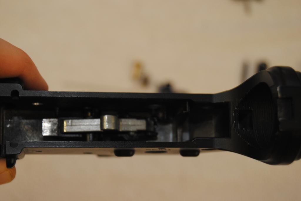 [/URL [/URLInstall Trigger housing into the middle of the lower receiver ================================================== ========= Step 2: Part A  Look at notch in this pin. The notch must be on the side of the receiver with the selector switch. There are three pins, each a different size. So it's impossible to mix up the pins. ================================================== ========= Step 3:  Install Pin ================================================== ========= Step 4:  Install the Selector Switch into the lower receiver. It should be easily inserted with minimal resistance. ================================================== ========= Step 5:  Now install the auto sear and Valve Lock Plate. The Valve lock plate should be closest to the selector switch then the auto sear. You may notice the Auto sear has a very long spring. Please look at the picture below to see where it goes.  ================================================== ========= Step 5: Part A  There is an extrusion in the receiver where the auto sear spring sits on. ================================================== ========= Step 6: Install the pin for the Auto sear above the Selector Switch. ================================================== ========= Step 7: Check your valve knocker, If the housing has come apart please follow the next few steps. If it's still in one piece please leave a side for now. ================================================== ========= Step 7: Part A  This is the valve knocker and it's spring. ================================================== ========= Step 8: Part B  You are going to twist around the spring and let it sit on the small extrusion on the valve knocker. ================================================== ========= Step 9: Part C  With the spring properly installed. Please take a look at the orientation of valve knocker. If you press down on it and it should return to it's original position. If it doesn't you probably have the valve knocker facing the wrong way or installed upside down. ================================================== ========= Step 10:  Hands down the hardest part about this reassembly process for the entire gun. Now this step requires three things to be inserted at the same time. Kind of hard to do as we only have two hands. The picture labels what order the parts go in. It was very difficult to take a picture by myself going through the motion so I'm going to do my best to explain it in writing. So the hammer and hammer spring goes in first. The spring arms will go on the left and right of the trigger housing. You will have to compress it while swinging over the Valve Lock Plate. The Valve Lock Plate must be under the Valve Knocker assembly. With those pieces side by side now install the valve knocker assembly. All the parts should sit parallel with each other so that when the pin is installed and it will secure all three parts. When holding down the hammer and spring you can snap it to the disconnector of trigger assembly making it a little bit easier to control the tension. ================================================== ========= Step 10: Part A  This picture shows the valve knocker assembly in place while I'm pushing the hammer and spring into place. When I have it in place I will swing over the Valve Lock Plate and lift the Valve knocker assembly until it falls underneith. ================================================== ========= Step 10: Part B  While applying pressure to the whole assembly so it doesn't explode. Install the pin. See how the notch is on the side with the selector switch. ================================================== ========= Step 10: Part C  Install the Valve Lock Plate Spring. There is a small wall behind the auto sear. You are going to insert the first part of the spring there. There is a gap between the auto sear and valve lock plate. The spring will go in between those parts. ================================================== ========= Step 10: Part D  Make sure the spring is under the Valve Lock Plate as shown above. ================================================== ========= You just did the hardest part of the assembly. At this point run a few test fire of the trigger assembly. Make sure the disconnector is working properly and that the hammer clicks down. Switch the selector to semi and auto and make sure it fires on both. Once you do that you can carry onto assembling the rest of the lower. ================================================== ========= Step 11  Install the trigger guard by installing the pin as pointed in the picture. ================================================== ========= Step 11: Part A  This part of the trigger guard has a spring detent. You must hold it down while you swivel it back into place. It will snap in once it's in position. ================================================== ========= Step 12  Install the Magazine catch spring on the right side of the lower receiver. ================================================== ========= Step 12: Part A  On the other side install the Magazine catch. ================================================== ========= Step 12: Part B  Install the button and turn it clockwise until it's just about to seize on the lower receiver. ================================================== ========= Step 12: Part C  At that point push the button all the way in and spin the magazine catch a few rotation so the spring is no longer showing on the other side. ================================================== ========= Step 13  Install the Take Down Pin so just the lip of the pin is in the hole. Notice the small hole high lighted. The parts below will be installed there. ================================================== ========= Step 13: Part A  This is the order you will install the detent, spring and screw. ================================================== ========= Step 14  Install the Buffer Retainer and Spring. Look at picture below for correct orientation.  ================================================== ========= Step 14: Part A  Push down on Buffer retainer and install buffer retainer screw. If installing into a new metal lower the threads need a little bit of elbow grease to get through. ================================================== ========= Step 15  Install the Selector Fire Detent and Spring   ================================================== ========= Step 16  Install Pistol grip. Make sure not to bend the spring. The pistol grip should slide on with a little bit of force. ================================================== ========= Step 17: Overview of Pistolgrip Spring/Pin  This is the screw and washer to install in the top of the pistol grip. ================================================== ========= Step 17: Part A Install Pistol Grip Install Pistol grip screw and washer. Make sure there is no play in the pistol grip by make the screw tight. WARNING if this is a plastic lower receiver, be careful as you can strip the hole by over tightening ================================================== ========= Step 18: Install Bolt Catch spring  Place the bolt catch spring into the hole right above the magazine catch. As where high lighted. ================================================== ========= Step 18: Part A: Bolt Catch  Install the bolt catch so the pin hole lines up ================================================== ========= Step 19: Part B: Bolt Catch Pin  Install pin for bolt catch. ================================================== ========= Step 20: Brass Tube  Install brass tube by turning clockwise. ================================================== ========= Step 20: Part A: Installation  Install the Brass tube until its snug on the Buffer Retainer. Then counter-clock wise a quarter turn. The Buffer Retainer should freely go up and down. If it's seized, continue to loosen the buffer tube until it's free. ================================================== ========= Step 21: Receiver End Plate  Install Receiver End Plate. ================================================== ========= Step 22: Receiver Extension  Slide on the Receiver Extension until it locks with Receiver End Plate. ================================================== ========= Step 23: Receiver Extension Cap  Install the Receiver Extension cap as tight as you can with your finger strength. Not to be confused with arm strength. ================================================== ========= Step 23: Part A: Receiver Extension Screw  Install Receiver Extension Screw once the cap has been installed and tightened. Do not over tighten this screw as it can easily strip. ================================================== ========= Step 24: Stock  Install the stock by pulling down on tail end of the Release Lever. ================================================== ========= Step 25: Buffer Spring  Install the tapered end of the spring into the Buffer Tube first. ================================================== ========= Step 25: Part A: Buffer  Install the buffer into the spring as shown in the picture. ================================================== ========= Step 25: Part B: Installation of Buffer  Simply push the Buffer over the Buffer Retension and it will lock in. If you installed the Buffer Retension backwards you'll notice that the buffer will freely shoot out. ================================================== ========= Barrel Group/Upper Receiver Reassembly Step 1: Hop up bucking  You will notice the bump or hump on the hop up rubber. Make sure that lines up with the opening on the inner barrel. ================================================== ========= Step 1: Part A: Hop up Chamber  Install the left and right side of the hop up chamber ================================================== ========= Step 1: Part B: Brass Ring  Install the brass ring. This part is an extremely tight fit. It may take you some time to get on. I use my flat head screwdriver to tap it down. ================================================== ========= Step 2: OPTIONAL: Ejection Port  For those of you who did the optional ejection port. Begin by putting the ejection port in place and slide the rod just before it starts to become visible again in the middle. ================================================== ========= Step 2: Part A: Ejection Port Spring  Remember the short side goes up and long side down. Note that the ejection port wants to swing open and not remain closed. If it does that that you installed the spring incorrect. ================================================== ========= Step 3: Upper Receiver  Now get the upper receiver, We will beging to install the hop up ================================================== ========= Step 4: Hop Up Base  Install the hop up base where located in the picture above. The tall end of should be facing inside the receiver. Spring side should be closest to the barrel. ================================================== ========= Step 4: Part A: Installation of Hop up Base and Spring  Hop up base and spring installation. ================================================== ========= Step 4: Part B: Hop up Plate  Install the hop up plate so that the bump is installed in the spring as shown in the picture. ================================================== ========= Step 4: Part C: Feeding Lamp  Install the feeding lamp to secure the Hop Up Plate from moving. ================================================== ========= Step 4: Part D: Hop up Adjuster and Spacer  The Hop Up Adjuster and Spacer fit together (Male and Female) ================================================== ========= Step 5: Part E: Installation of Hop up Adjuster/Spacer  Make sure the Hop Up Plate is underneath the Hop Up Adjuster. ================================================== ========= Step 5: Part F: Install Feeding Lamp Screw  Don't forget this screw or your hop up will fall apart! ================================================== ========= Step 6: Inner/Outer Barrel  This step may have fast forwarded a little bit. Combine the Outer and Inner Barrel and Make sure the inner barrel is secured by the grub screw. When installing the barrel make sure the exposed hop up rubber is facing up! If not you can break your Hop Up Plate. **WARNING! Make sure your hop up plate is completely flat when installing the barrel, AKA Make sure the wheel is in the OFF position** How do you know when it's off is you rotate the wheel counter-clock wise until it locks. When that happens the hop up is zero.** ================================================== ========= Step 7: Install Barrel Assembly to Upper Receiver with Delta Ring  Install the Delta Ring with the AR Wrench tool. Make sure you can put the gas tube through the Delta Ring. ================================================== ========= Step 8: Gas Tube  Put the tapered end into the receiver ================================================== ========= Step 9: Hand Guard Retainer Cap  Install the Hand Guard Retainer cap so it looks like the photo above. ================================================== ========= Step 10: Front Sight Post  Install the Front Sight Post. It should slip onto the gas tube. Install the pins ================================================== ========= Step 11: Outer Barrel Extension/Nickle Ring/Flash Hider  These parts should all basically slip on and the flash hider will tighten the entire assembly. ================================================== ========= Step 12: Hand Guards  Install the hand guards the same way they were removed. Pull back on the delta ring towards the receiver. ================================================== ========= BOLT REASSEMBLY STEP 1: Cylinder  To install the Cylinder begin by just tap the pin in slightly where highlighted below.  ================================================== ========= Step 1: Part A: Installation  Look down the bolt cylinder to make sure the pin is going through the spring. You may need to tweezers or a small tool to slightly pull the spring into position. I managed with using a small flat head. ================================================== ========= Step 2: Piston  The piston must be installed flush with the base of the bolt. You will see a circular extrusion from the bolt. The piston must be 100% flush with it when tighten. If not the cylinder will rub up and down awkwardly causing damage to the piston and unwanted firing results. The use of blue lock tight is highly recommended during installation so it does not fall loose over time of use. There is a reason they used red lock tight! ================================================== ========= Step 3: Valve Spring, Floating Valve and Valve Pin.  This is the order you will install the parts. The cylinder has a hole where you will drop the spring in. Shake the cylinder until the spring falls in.  When it does throw the floating valve in. This part will require you to hold it in place with a screw driver while you install the pin ================================================== ========= Step 3: Part A: Installation  Put your screw driver in the gas port to hold the valve in while installing the pin/screw. ================================================== ========= Step 4: Return Belt  Place the return belt on the fin of the bolt carrier group. ================================================== ========= Step 5: Guide Rod  Install the Guide Rod as shown in the picture ================================================== ========= Step 6: Charging Handle Do the complete opposite of what the picture says. You will slide it on at step 2 and let slip onto the end of the guide rod. ================================================== ========= Step 7: Bolt Carrier Group into Upper Receiver Again do the opposite of the what the photo says. Push it into the receiver making sure it's flush the end of the receiver minus a small little square tab that will fit into lower receiver. ================================================== ========= Step 8: Top and Bottom Receiver  Push the pins and your gun should be all done now. Congratulations. You've made it through. Hopefully this guide was helpful in taking apart your KJW M4. For those of you who may notice some parts on this gun look different from yours. This take down was done during a repair, it had a broken hop up. This gun also has two upgraded parts. The Cradle X-Piston and Velocity Reducers. Now if during this process you've lost or found a broken part the best course of action is to contact KJW directly. Their email is kjworks@ms47.hinet.com I've been in contact with them throughout this process. Sometimes their response is a little slow but the parts are cheap, so is the shipping. One time I've received a package from them within two weeks. They have everything in stock. So if you have patience and want to save a little money. This is the option! MODIFICATIONS TOP DOWN CENTER HOP-UP MOD  Does your gun lack the ability to over-hop .25's? Well the KJW is known for it's poor proprietary hop up. This mod will allow you to use a grub screw to adjust the hop up plate. To do this mod you will need a Tap: **INFORMATION UNKNOWN** Drillbit: **INFORMATION UNKNOWN** Grub Screw: **INFORMATION UNKNOWN** I'll do my best to find the information for you guys. I've done it before I just have to find the parts and see what the specs are. And most of all CONFIDENCE! To do this mod the Upper Receiver must be COMPLETELY STRIPPED DOWN. The picture shows you to mark an X on the last pictany rail. The middle of the X is where you will drill your pilot hole. Try to be exact as possible. Do what ever is necessary to make the drill go perfectly vertical. Once the hole is drilled you will need a tap. The tap is always bigger than the pilot hole. The tap carves grooves into the hole creating threads. Slow and steady on this part, again make sure your tap is perfectly vertical with the hole. You don't want crooked threads. Once the tap has done its work you are basically done. Match up the TPI on the tap to a grub screw you are going to buy. TPI stands for Threads per Inch. If you have a grub screw that has lets say 26 TPI and the hole you just tapped is 32 TPI, you will strip the hole. I do not have to remind you that you only have one shot at this. Where can I purchase these parts? I got my tap and dye kit from Princess Auto for 60 bucks on sale. Normally it's around 120. If you are cheap you can buy it, use it then return it. But retail frowns upon that. Drill and Grub Screw I made a special order through Fastenal. Cost me $7-12 with taxes for both. You could also try Spainer and other local hardware stores/bulk bolts/screws/nuts stores. Where can you buy confidence? Ask your airsoft community if their is a gun doctor comfortable with doing this procedure. Cradle offers this MOD for $45 but you pay shipping there and back. So it will probably cost $70-80 + you risk the possibility of having it seized by customs even though it's legal to import. AVAILABLE UPGRADES FOR THE KJ-WORKS M4 GBBR (THESE ARE IN COUNTRY of CANADA) EXCEPT for CRADLE which is US *This list can be updated with your help! Please send me a link if you find more Canadian retailers selling KJW M4 GBBR parts* **If enough demands ask I will include import retailers as well.** Cradle Velocity Reducer http://www.cradleairsoft.com/shop/ve...-reducer-kjwm4 Cradle X-Piston http://www.cradleairsoft.com/shop/x-ring-piston Cradle V1+Bolt Carrier Group http://www.cradleairsoft.com/shop/v1bcg Cradle Polybelt http://www.cradleairsoft.com/shop/polybelt RA-TECH V2 Bolt Set http://www.airsoftparts.ca/store2/in...oducts_id=2323 Hephaestus Steel Charging Handle A+B http://www.airsoftparts.ca/store2/in...oducts_id=2488 http://www.airsoftparts.ca/store2/in...oducts_id=2489 RA-TECH 363mm - 501mm 6.03-6.01mm TBB http://www.airsoftparts.ca/store2/in...oducts_id=2371 http://www.airsoftparts.ca/store2/in...oducts_id=2322 http://www.airsoftparts.ca/store2/in...oducts_id=2171 RA-TECH Blue Hop-Up Rubber http://www.airsoftparts.ca/store2/in...oducts_id=2370 RA-TECH NPAS http://www.airsoftparts.ca/store2/in...oducts_id=2047 KJW Metal Lower Receiver https://www.007airsoft.com/product.p...link=&view=236 KJW Replacement Tinted(Plastic) Receiver https://www.007airsoft.com/product.p...link=&view=225 KJW GBBR Magazine https://www.007airsoft.com/product.p...link=&view=117 http://www.airsoftparts.ca/store2/in...oducts_id=2121 https://www.buyairsoft.ca/accessorie...-m4-gbb-r.html http://www.cansoft.biz/www/product_i...roducts_id=172 Random KJW GBBR Parts: http://www.cansoft.biz/www/index.php?cPath=119_120 https://www.007airsoft.com/manufacturer.php?man=2
__________________
Bolt Action Level 2 Certified Last edited by Olisharpeye; July 6th, 2013 at 20:02.. Reason: Duplicate Photos, Grammar |

|

|
|
July 6th, 2013, 19:10
|
#2 |
|
Banned
|
WOW. I always wanted to know what the KJW works GBBRS looked like form the inside this is awesome thanks >
 I wonder if theres a way to mod the fire pin assemble to fit inside a WA |
|
|
|
|
July 6th, 2013, 22:13
|
#3 |
|
Awesome thread !! Lots of work involved, nicely done !!
|
|
|
|
|
|
October 13th, 2013, 20:27
|
#4 |
|
|
Just wanted to say thanks for posting this!
|
|
|
|
|
April 9th, 2015, 05:11
|
#5 |
|
Thanks!
Terrific post man! Thank you!
|
|
|
|
|
 |
|
||||||
| Bookmarks |
|
|
 |
|